Skip to product information
-
 Media gallery
-
 Media gallery
-
 Media gallery


Sku:
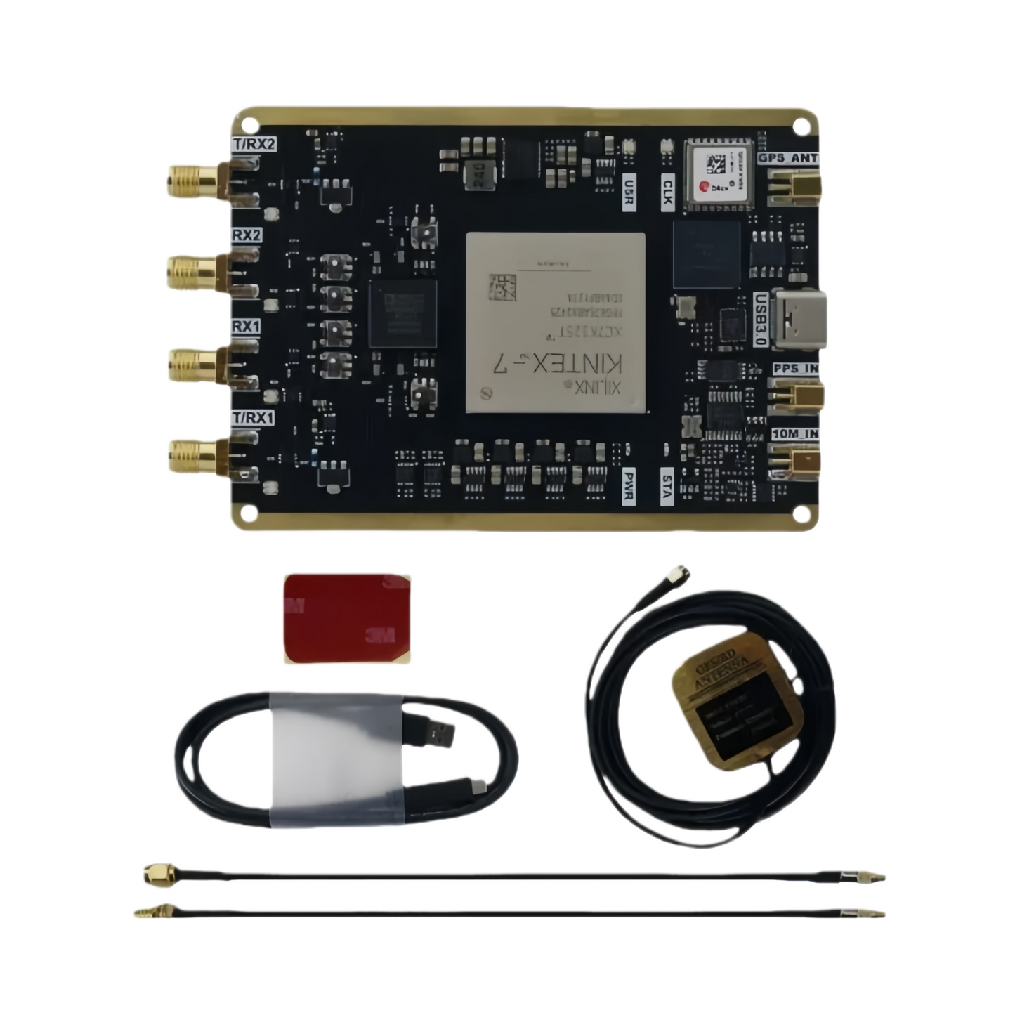
B210 USRP with XC7K325T + AD9361 and Onboard GPS Module for SDR Wireless Communication Development
- Sale price
- $305.00
- Regular price
-
- Regular price
- $305.00
- Unit price
- per
-0%
Vendor: YanTechLab
Only
9
items in stock!
Out of stock!
Guaranteed safe checkout
Couldn't load pickup availability
Description
Description
Optimized USRP B210 SDR | Kintex-7 | USB 3.0 Type-C | GPS & PPS Support
This USRP B210-compatible SDR platform is an optimized and upgraded design based on the original reference hardware. It replaces the legacy Spartan-6 FPGA with a newer Kintex-7 (K7) series device, enabling full Vivado development support while maintaining compatibility with official B210 functionality.
Functional Overview
| FPGA Architecture | Upgraded from Spartan-6 to Kintex-7 , supporting Xilinx Vivado toolchain and modern IP cores. |
|---|---|
| USB Interface | USB 3.0 Type-C interface with a maximum real-time data bandwidth of 56 MHz . |
| RF Front-End | Identical RF front-end architecture to the official B210, using band-segmented RF design . RF traces are simulation-optimized for signal integrity. |
| Reference Inputs | Supports PPS and 10 MHz external reference inputs. |
| GPS Module | Onboard GPS module integrated, capable of replacing external PPS input. |
| GPSDO Support | GPSDO socket removed to reduce size and simplify the design. |
| Mechanical Size | Compact form factor: 70 × 97 × 11.5 mm . |
Usage Notes & Differences from Official B210
| FPGA Bitstream | Before use, replace the PC-side usrp_b210_fpga.bin file with the provided version. |
|---|---|
| GPSDO Module | External GPSDO modules are not supported . |
| PPS Priority | The onboard GPS PPS signal has higher priority than the external PPS input. When GPS is locked, the external PPS input is disabled. |
Interface Description
| GPS | GPS antenna input, MMCX connector |
|---|---|
| USB | USB 3.0 data connection to host, Type-C connector |
| PPS | External PPS input, MMCX connector |
| 10 MHz | 10 MHz reference clock input, MMCX connector |
| TRX1 | TX or RX Channel 1, SMA connector |
| RX1 | RX Channel 1, SMA connector |
| RX2 | RX Channel 2, SMA connector |
| TRX2 | TX or RX Channel 2, SMA connector |
| FPC Connector | JTAG debug interface and extended GPIO |
| POWER LED | Power indicator LED, solid red when powered |
| STATUS LED | Status LED, blue after firmware is loaded |
| CLK LED | PPS indicator LED, red flashing synchronized to selected PPS source |
| USER LED | Reserved, user-defined |
| TRX1 LED | TX/RX indicator, red during TX, blue during RX |
| RX1 LED | RX indicator, blue during reception |
| RX2 LED | RX indicator, blue during reception |
| TRX2 LED | TX/RX indicator, red during TX, blue during RX |
Documentation & Resources
Complete documentation and support materials are available via:
t.me/YanTechLab
Terms and conditions
Terms and conditions
Shipping Information
Orders are prepared within 48 hours. Fast small-parcel logistics are used for international shipping.
- USA / Europe: approximately 8–14 days (subject to variation)
- Any abnormal situations will be communicated via email promptly
Returns & After-Sales Policy
If you have any questions after receiving the product, please contact us immediately. Returns or exchanges will be processed according to our return policy. Thank you for your understanding.
Documentation & Technical Support


Size Guide
Please select a page or Add metafield
Popup Text
lorem Loren
Notified by email when this product becomes available

B210 USRP with XC7K325T + AD9361 and Onboard GPS Module for SDR Wireless Communication Development